10+ led block diagram
Block Diagram The demonstration board showcases the features of the Intel Agilex I-Series device in the F2957 FBGA package. 10 LEDs LED Driver LED Driver FPGA Host MCU Video 10 LEDs per string 16 LED strings total 160 LEDs I 80mA 20 Monitor Screen USB DVI High speed differential interface SPI Edge-Lit.
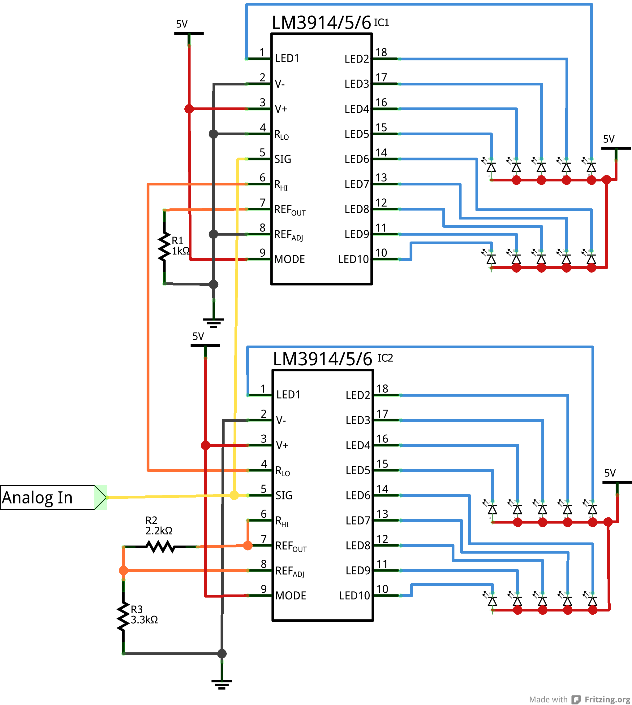
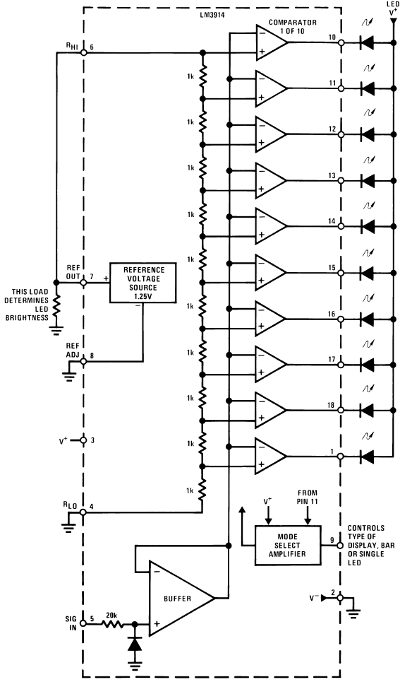
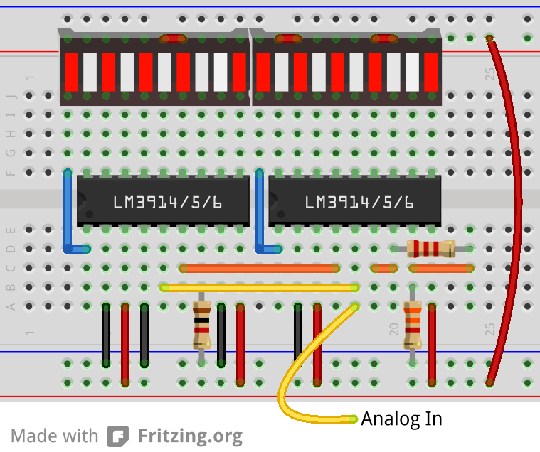
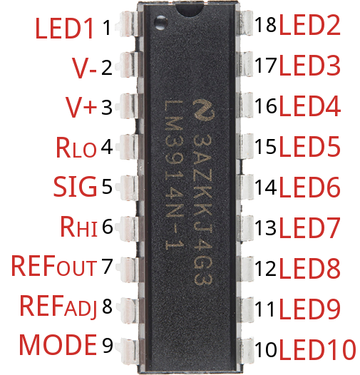
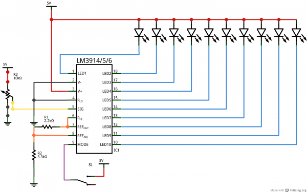
Dot Bar Display Driver Hookup Guide Learn Sparkfun Com
Pick a Block Diagram Template Start Wondershare EdrawMax on your computer ensure that New is selected in the navigation pane at the left confirm that Basic Diagram is selected in the diagram types list in the middle and click to select Block Diagram from the top row of the right window.
. Understanding the block diagram of an equipment will give you an advantage in solving a problem faster. For example the functional block diagram of a 4-CH LED driver RT8510 used in notebook computers is illustrated in Figure 2. If any object is existing at out of the.
Its structure provides a high-level overview. If you use the 9V battery. It can be used to better understand a circuit of a motherboard.
Download scientific diagram Block diagram of LED panel. Led Block Diagram December 04 2018 Get link. R1 is a bleeder resistor which drains the stored charge from C1 when the AC input is switched OFF.
10 Con figuration F PGA Ba nks F PGA Pow er DDR3 Me mory Pla tform MCU 4 US B F IF OS PI P ow er Tree F PGA Ba nks 11 Pow er Re gulation 12 Pow er regulation 13 US B JT A GUA RT D. Here I have used a 9-volt adapter to supply the circuit. In the circuit 047uF400V Polyester capacitor C1 reduces the mains voltage.
LED Flasher Circuit Diagram. These devices feature R-tile transceivers. Digital to Analog Converter DAC Types Working and Applications.
Put up through admin at March 2 2016. The buzzer and LED are used as an indicator. Block Diagram Of A Complete Led Reliability Test System.
Typical LCD TV Block Diagram. LED LCD TVs consume less power than CCFL LCD TVs Figure 2. CD4711 is made from CMOS logic and the NPN transistor based output devices.
The following figure shows the top-level block diagram for the Zynq UltraScale RFSoC. Zynq UltraScale RFSoC Top-level Block Diagram The Zynq UltraScale. Led Block Diagram December 19 2018 Get link.
Panasonic Led Block Diagram Keywords. The upper block is Boost Converter providing the voltages needed for LED strings and the lower block is Constant Current Dimming Controller. It has properties of low power.
Dancing Bi Color LED Circuit. Seven LED segments of the display and their pins are. CD4711 IC is a BCD to seven segment decoder driver integrated circuit.
For your information I used to understand an equipment block diagram first before i. It is used to design new systems or to describe and improve existing ones. Panasonic led block diagram automotive applications mouser led lcd backlights explained cnet interface converter si 35usb lineeye panasonic se.
A block diagram is a specialized high-level flowchart used in engineering. Generally we use small voltage bulbs in. A string of five LED is driven using a capacitive transformer less power supply.
Calibration of 10 Level Battery Charge Indicator Circuit Connect the 15V variable power supply at B1 point at place of battery Set 3V to variable power supply. The Block Diagram For The Srl16s Based Implementation Of Led. Today I will give you a Collection of All Smart Universal Brands Lcd Led Tv Board Schematic Diagram Circut Diagram.
The Arduino reads the data from the Sensor and prints the measuring distance on the display. In this matrix we can select any LED by corresponding row and column number. 4017 LED chaser Schematic Diagram This the schematic of the 10 LED chaser with only 4017 IC.
Heres a block diagram of a Digital LCD TV and if possible you may print it out for future use. Block Diagram of LED Flasher Circuit. This project consists of two.
By Jestine Yong on January 4 2011. Block Diagram Factors. Now from the control palette on the front panel select Boolean and then select Round LED as shown in the figure below Figure 2.
That image Led Block Diagram The Wiring Diagram Readingrat intended for Led Wiring Diagram previously mentioned will be classed with. LED Blinking Circuits Applications. This is just a LED lamp circuit that can be operated from the mains voltage.
Dot Bar Display Driver Hookup Guide Learn Sparkfun Com
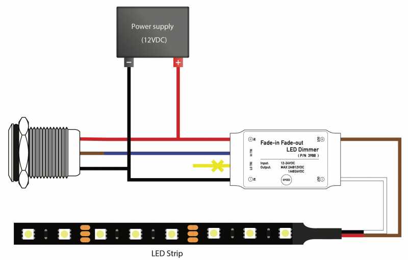
Led Dimmer Fade In Fade Out Led Dimmer From Oznium
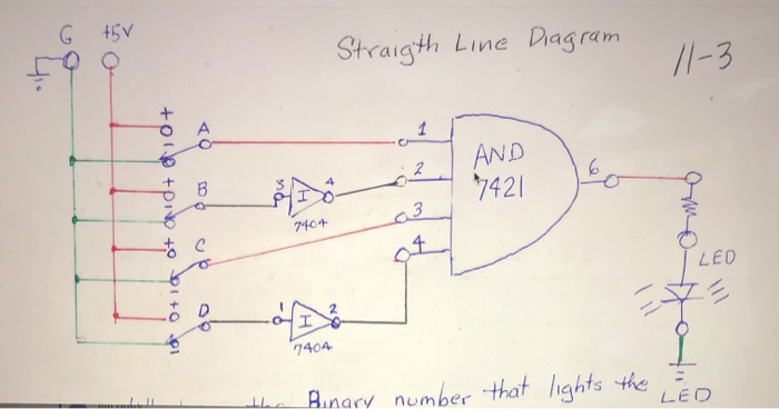
Solved Gt5v Straigth Line Diagram 11 3 And 2 4 B Ne 7421 Chegg Com

Top 10 Simple Electronics Projects For Complete Beginners

High Power Led Driver Circuits 12 Steps With Pictures Instructables
Design And Circuit Troubleshooting Microtype Engineering

Led Circuit Wikiwand

High Power Led Driver Circuits 12 Steps With Pictures Instructables
Dot Bar Display Driver Hookup Guide Learn Sparkfun Com
Dot Bar Display Driver Hookup Guide Learn Sparkfun Com
Dot Bar Display Driver Hookup Guide Learn Sparkfun Com
Dot Bar Display Driver Hookup Guide Learn Sparkfun Com

Image Result For Circuit Diagram For 9v Adapter Power Supply Circuit Electronics Basics Power Supply
Dot Bar Display Driver Hookup Guide Learn Sparkfun Com
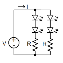
Led Circuit Wikiwand

Arduino Led Light Chaser 10 Led Code Circuit

10 Light Wiring Diagram Car Devre Semasi Elektronik Devre Elektrik